Level up your PV modeling. Check out our library of on-demand webinars. Watch now →
✕

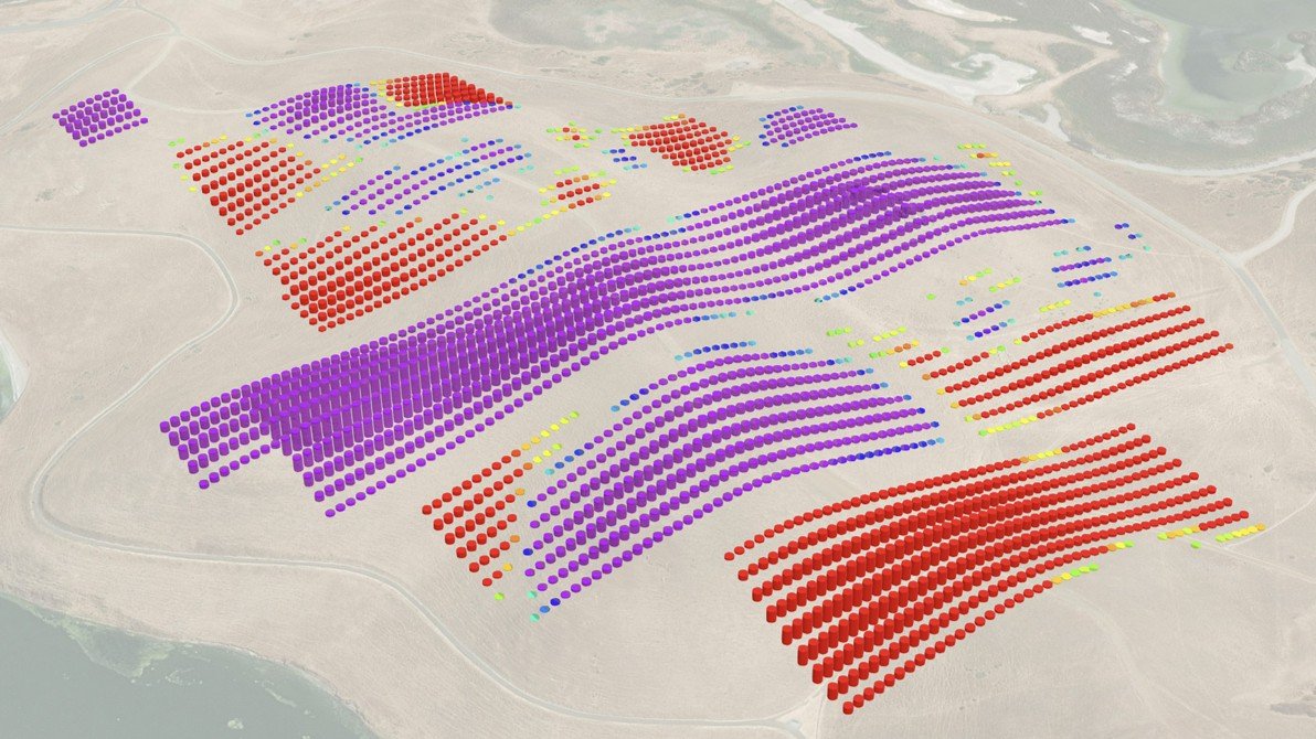
In utility-scale solar projects, earthwork isn't just another cost item — it can quickly become a logistical challenge and even a permitting obstacle. Accurate earthwork estimates help reduce risk and allow project teams to plan for costs and schedules with far greater confidence. Yet many projects still rely on flat-map assumptions that overlook real terrain complexity. The result? Higher project risk, cost, and schedule overruns, and uncertainty during permitting.
This blog explores key concepts in earthwork and demonstrates how grading assessments are performed in Terrain Pro. Whether you're choosing between fixed-tilt and terrain-following trackers or evaluating structural outputs such as pile maps and steel quantities, Terrain Pro enables you to measure, visualize, and refine earthwork with remarkable precision.
A disturbed area refers to any portion of the site where the land surface is altered by construction activity. This disturbance can occur as a result of clearing, grading (cut and/or fill), or other construction processes. Disturbed area is an important metric for many project stakeholders because these areas are more susceptible to erosion, can lead to the loss of habitat and groundcover, and affect the overall aesthetic of the landscape.

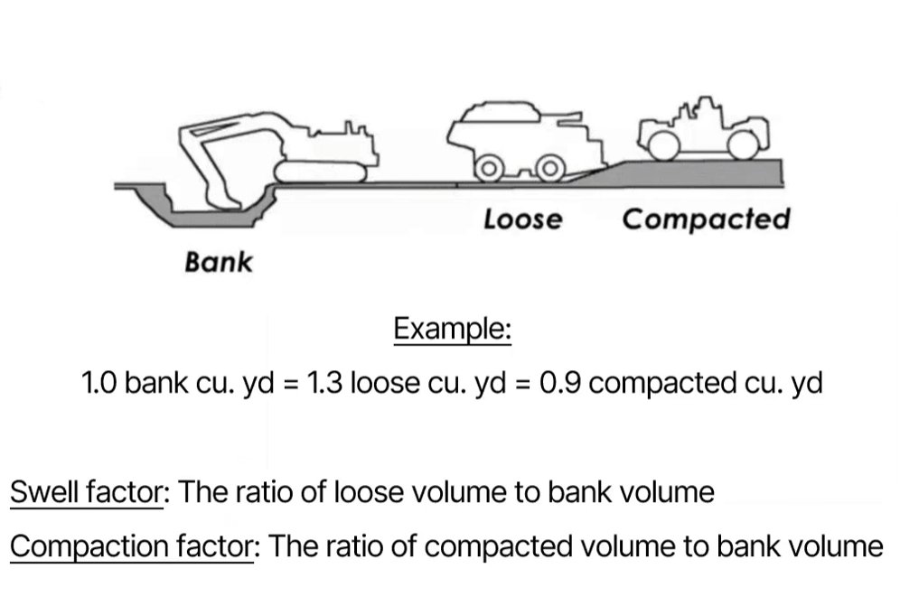
Soil does not maintain a constant volume as it is excavated, hauled, and compacted. For estimating earthwork on utility-scale solar sites, it's important to distinguish between three key volume states:
Bank Volume
The bank (or in-situ) volume is soil in its natural, undisturbed state. All production, swell, and compaction factors are referenced to bank volume because it reflects the actual on-site conditions prior to construction activity.
Loose Volume
When soil is excavated, it breaks apart, and the void spaces between particles increase. This causes the soil to swell — in other words, the loose volume is greater than the bank volume. The swell factor is site-specific and can be provided by the geotechnical engineer drafting the geotechnical report. Alternatively, the swell factor can be indexed to common soil types. Swell factors range from about 12% for sand and gravel to >60% for rock formations.
Compacted Volume
When soil is placed and compressed to meet a specified density (e.g., 90-95%), its volume decreases relative to the bank state. The compaction factor is represented as the ratio of the compacted volume to the original volume.
Depth of cut is the amount of soil that must be excavated from an area to reach the design grade. Greater cut depths typically increase construction costs because they may require larger or additional excavation equipment, stabilization or protection of cut slopes, and specialized techniques such as benching, where stepped terraces are cut into the slope to maintain safety and prevent slope failure. In rocky or hard soils, deeper cuts can also lead to higher production times or the need for ripping or blasting.
Depth of fill refers to the amount of imported or onsite material needed to raise a low area to the target grade. Deeper fills often increase cost due to thicker lifts requiring engineered compaction, the potential need for imported borrow if onsite cut material is unsuitable, and associated drainage or stabilization improvements. For example, deeper fill areas may require geotextiles, reinforced fill, or underdrains to manage moisture and maintain long-term stability, especially in fine-grained or saturated soils.
Understanding where the site requires deep cuts or fills is essential for estimating earthwork quantities, balancing cut and fill volumes, designing site drainage, and also for scoping geotechnical investigations. Knowing and communicating the areas, and depths of cut/fill, to the geotechnical engineer can help inform the geotechnical study and remove project risk.

A pile (also called a pier in some regions) is a deep foundation element installed into the ground to support the solar racking or tracker system. In utility-scale solar construction, piles are typically driven steel posts that transfer structural loads — such as wind, snow, and mechanical loads from the tracker — into the underlying soil.
Piles must achieve a required embedment depth, pile reveal, and bearing capacity to ensure long-term stability of the solar array.
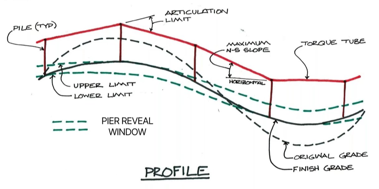
A pile or pier reveal is the portion of the steel above grade. In addition to achieving the required embedment depth, piles must also meet the specified pile reveal — the portion of the pile extending above finished grade — to comply with the tracker manufacturer's design requirements.

The pile (or pier) reveal window is the vertical distance between the maximum and minimum allowable pile reveals for a project. It defines how much variation in exposed pile height is acceptable across the site after installation.
This reveal window is sometimes referred to as the grading tolerance or the undulation tolerance, because it reflects how much variation in finished grade the project is willing to accommodate without requiring regrading or pile modifications.
Additionally, the minimum pier height is not arbitrary — it is driven by factors such as the required ground clearance of the modules, the overall module and torque tube geometry, the tracker's maximum stow angle (which defines the lowest corner of the array during high-wind stow), and any flood depth requirements specified for the site. These parameters ensure that the array maintains adequate clearance for safety, performance, drainage, and flood resilience.
The articulation limit is the maximum allowable change in slope from one bay to the next.
The maximum N-S slope is the maximum allowable slope of a given torque tube, or sometimes average torque tube slopes for a given tracker.
Earthwork is the hidden foundation of every utility-scale solar project. It dictates how well the array fits the natural terrain, how much material must be moved, and whether the layout is even constructible. Correct grading assumptions are essential to avoid redesigns, manage costs, and ensure long-term structural and operational performance.
Earthwork can be one of the largest variable cost drivers in site preparation. Overestimating cut/fill volumes inflates CAPEX and can misrepresent project viability. Conversely, underestimating leads to scope gaps, change orders, schedule delays, and strained EPC relationships. Accurate earthwork modeling ensures realistic budgets and reduces financial risks.
Terrain-following trackers like XTR require precise slope modeling to stay within articulation limits. Poor grading can reduce energy yield or violate mechanical constraints.
Earthwork volumes directly influence EPC costs and, by extension, the Levelized Cost of Energy (LCOE). Accurate grading estimation enables better financial forecasting.
Disturbed area and soil movement must be documented for environmental permits. Accurate earthwork data supports faster approvals and mitigates regulatory risk.
Tools like Terrain Pro allow developers to compare fixed-tilt vs. terrain-following layouts, quantify earthwork trade-offs, and select the most cost-effective configuration.
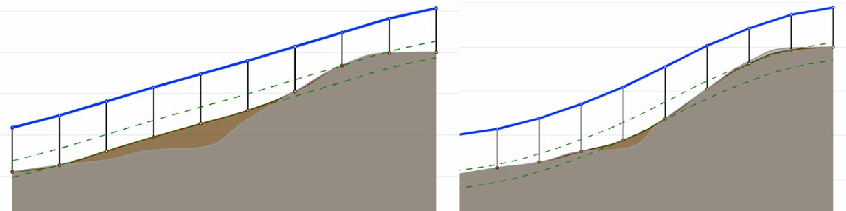
Tracker selection is not merely a mechanical decision but a negotiation with site terrain. Standard, non-terrain-following systems offer simplicity and predictability, but they often demand aggressive grading to flatten slopes. Terrain-following trackers, by contrast, adapt more closely to the site's natural contours, reducing earthwork but introducing complexity in design and articulation.
Understanding the trade-offs between these systems is essential for optimizing layout, minimizing cut-fill volumes, and ensuring structural feasibility. Terrain Pro allows stakeholders to simulate both configurations and quantify their impact on earthwork, pile embedment, and overall constructability. Check out the Earthwork Analysis Case Study in Terrain Pro for more information. Below, we will look at key differences between a fixed-tilt and a terrain-following tracker.
You can perform earthwork analysis in Terrain Pro using a Design Pro model, CSV file, DXF file, or PVCase BOM file. In the example below, we will be using a Design Pro model to complete the earthwork analysis.
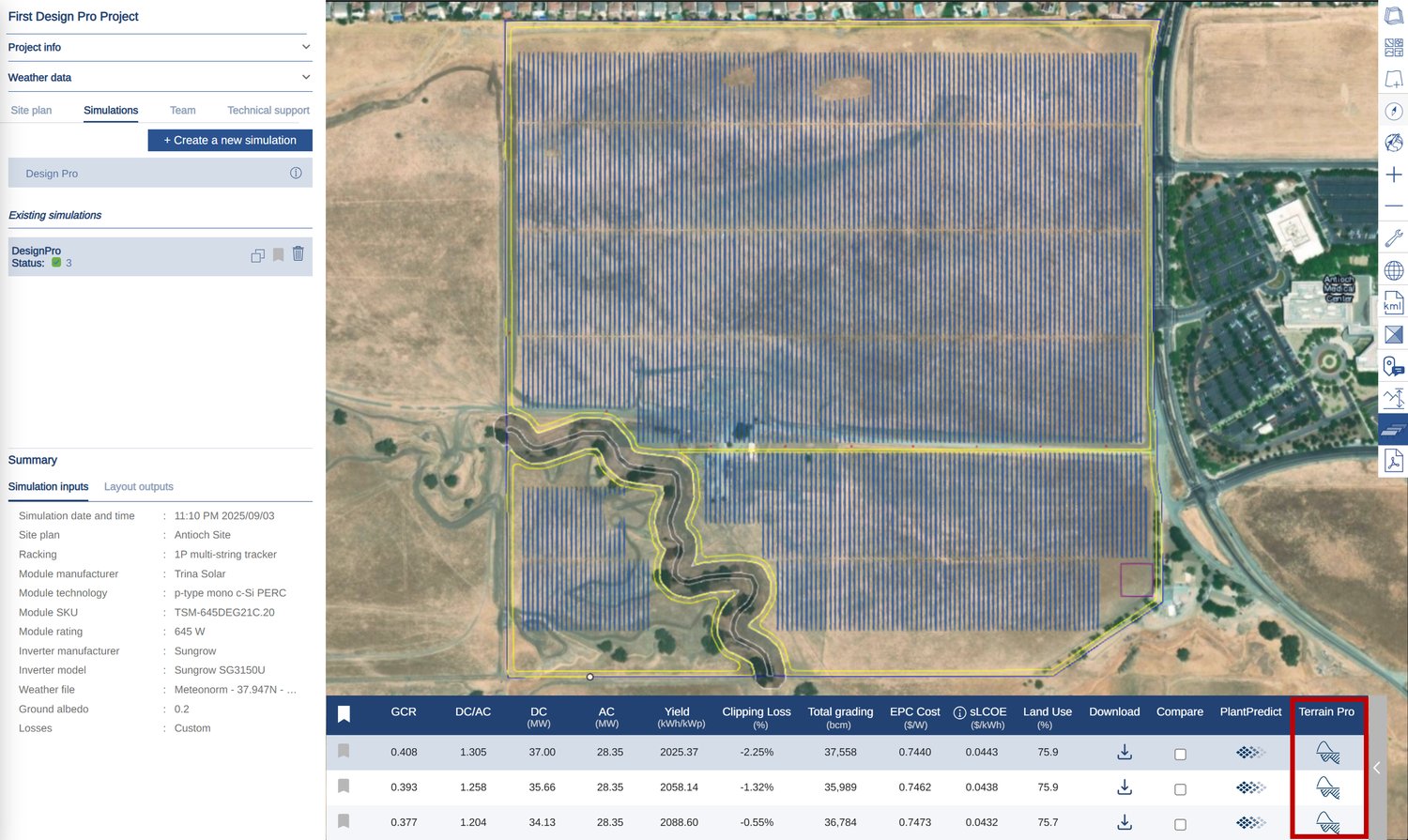
After opening or creating a Design Pro layout, click on the Terrain Pro icon for the earthwork scenario you wish to analyze. In this example, we will analyze the earthwork for the first scenario.
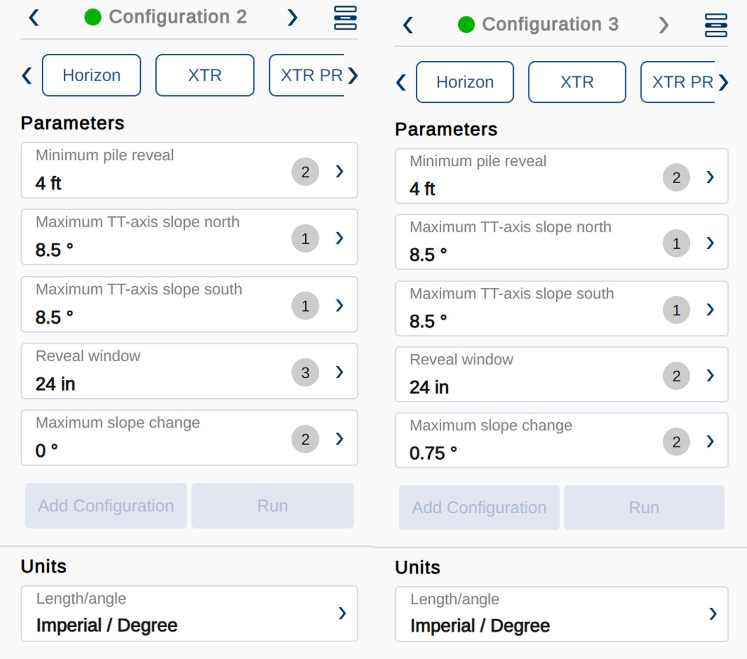
Once Terrain Pro opens up, you will notice a configuration table on the left side of your screen. For this sample project, we will analyze both a standard (non-terrain-following) and a terrain-following tracker. For the non-terrain-following tracker, we will select Horizon, and for the terrain-following tracker, we will select XTR. NexTracker manufactures both of these trackers.
After selecting the Horizon option, click the Add Configuration button, then the Run button. Repeat the process for XTR.
Once the earthwork analysis is complete, you will receive the Earthwork Quantities on the right side of your screen. To load the Earthwork Heatmap, click on the Earthwork button on the top center of your screen.
Below is the Earthwork Heatmap for Horizon parameters. We have kept the default Horizon parameters for this configuration. You will notice that we have 22,809 bcy of cut, 7,380 bcy of fill, and 15,430 bcy of net volume.
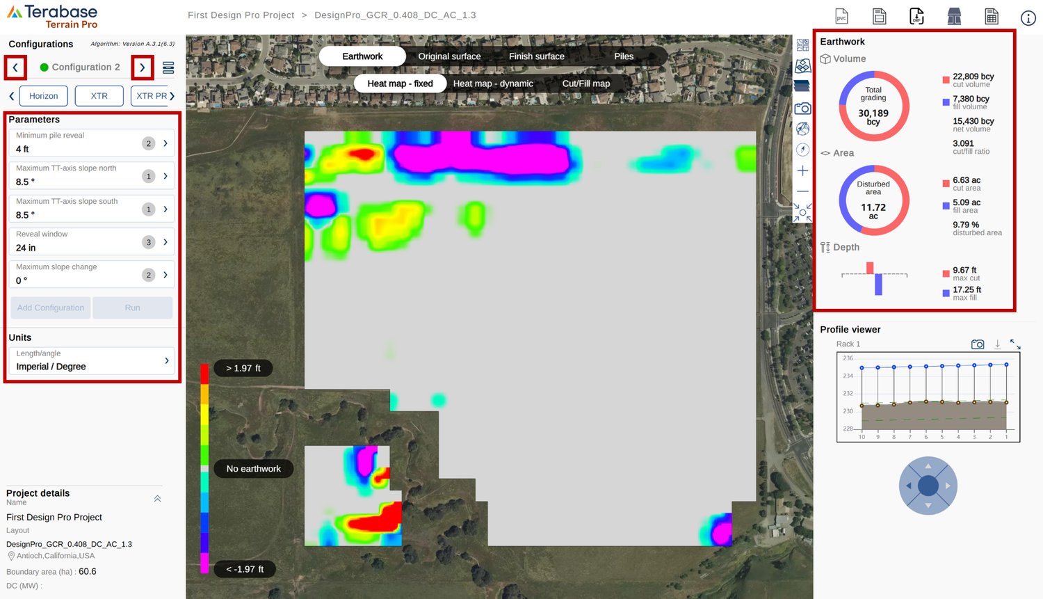
You can maneuver between configurations by clicking on the left or right arrow in the configuration box located on the left side of your screen. To switch to the XTR configuration, click on the right arrow of the configuration box. You will notice that the earthwork has significantly reduced. The cut volume is 5,505 bcy, the fill volume is 3,535 bcy, and the net volume is 1,869 bcy.

For each configuration, you have the option to export the following from the top-right corner of your screen:
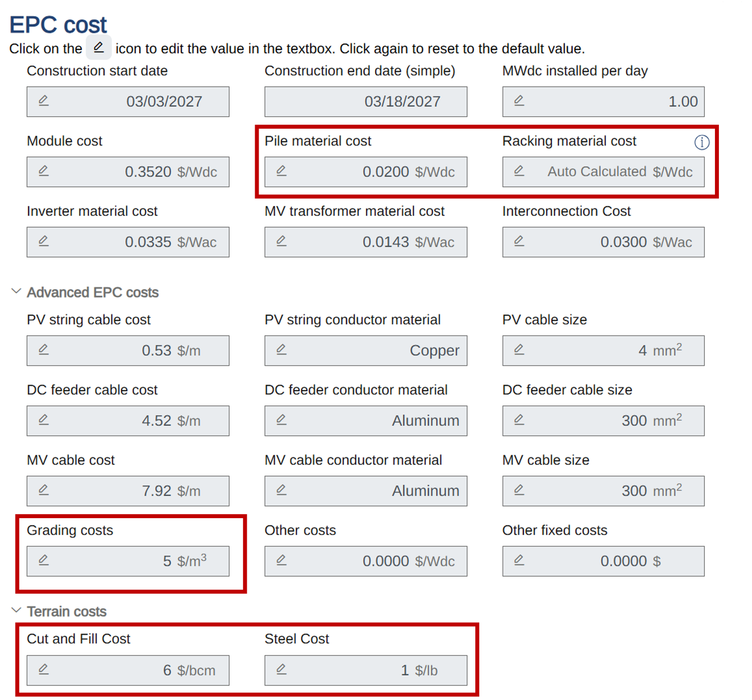
There are two important financial factors that every engineer must consider when planning earthwork for utility-scale solar projects. The first factor is the cost of earthwork for both terrain-following and non-terrain-following scenarios. The second factor is the cost of the terrain-following tracker compared to the non-terrain-following tracker.
To determine the best option, sum the costs of the trackers and the earthwork for each scenario. The option with the lower total cost is the ideal choice.
You can obtain the cost estimate for the tracker directly from the manufacturer or by using the advanced financial estimation tool offered by Design Pro. For the earthwork costs, including cut, fill, import, and export, you can refer to RS Means, consult an estimator, or utilize Design Pro's advanced financial estimation tool.
With Terrain Pro, you can visualize both the Original Surface and the Finished Surface of a site. The surface can be displayed as either a heatmap or with contour lines. Below, you can explore the Original Surface of the site, showcasing both the elevation heatmap and the contours.

There are two key Structural Outputs that you can get from Terrain Pro:
The Pile Map displays the location of piles on the site with an aerial background.

A Pile Binning Table organizes and quantifies the number of foundation piles required at different lengths or sizes. Terrain Pro also allows you to change the minimum embedment and section type.

To open the Pile Binning Table, click on the Pile Binning Table button located on the top-right side of the screen.

Earthwork may not always be the first consideration in the early stages of a project lifecycle, but it has an outsized impact on the success of utility-scale solar projects. Thoughtful grading and accurate terrain modeling influence everything from energy yield to structural integrity and overall project cost. Tools like Terrain Pro bring clarity to this process — streamlining planning, visualizing design trade-offs, and enabling data-driven decisions.
By deeply understanding site terrain and automatically accounting for the limitations of trackers, developers can minimize unnecessary cut-and-fill, avoid costly redesigns, and accelerate construction. Smart earthwork isn't just good engineering — it's a strategic business advantage that drives lower risk, lower cost, and higher project performance. Terrain Pro can help!
Join hundreds of organizations that trust PlantPredict for bankable energy predictions. Start with a free account, get a free trial of Pro features, or book a demo with our team.